Is this a problem? Like always…it depends, let’s take a look at an example:

Take a look at the topology above. We have three switches and a lot of VLANs. There’s 199 VLANs in total. If we are running PVST or Rapid PVST this means that we have 199 different calculations for each VLAN. This requires a lot of CPU power and memory.
When SwitchB is the root bridge for VLAN 100 – 200 and SwitchC for VLAN 201 – 300 our spanning-tree topologies will look like this:

SwitchB is the root bridge for VLAN 100 up to VLAN 200. This means that the fa0/17 interface of SwitchA or the fa0/14 interface on SwitchC will be blocked. I’ll have 100 spanning tree calculations but they all look the same for these VLANs…
The same thing applies for VLAN 201 – 300. SwitchC is the root bridge for VLAN 201 up to 300. The fa0/14 interface on SwitchA or SwitchB will be blocked for all these VLANs.
Two different outcomes but I still have 200 different instances of spanning tree running. That’s a waste of CPU cycles and memory right?
MST (Multiple Spanning Tree) will solve this issue. Instead of calculating a spanning tree for each VLAN we can use instances and map VLANS to each instance. For the network above I could do something like this:
- Instance 1: VLAN 100 – 200
- Instance 2: VLAN 201 – 300
MST works with the concept of regions. Switches that are configured to use MST need to find out if their neighbors are running MST.
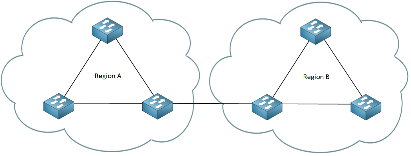
When switches have the same attributes they will be in the same region. It’s possible to have one or more regions and here are the attributes that need to match:
- MST configuration name.
- MST configuration revision number.
- MST instance to VLAN mapping table.
The MST configuration name is just something you can make up, it’s used to identify the MST region. The MST configuration revision number is also something you can make up and the idea behind this number is that you can change the number whenever you change your configuration. It doesn’t matter what you pick as long as it’s the same on all switches within the MST region. VLANs will be mapped to an instance by using the MST instance to VLAN mapping table. This is something we have to do ourselves.
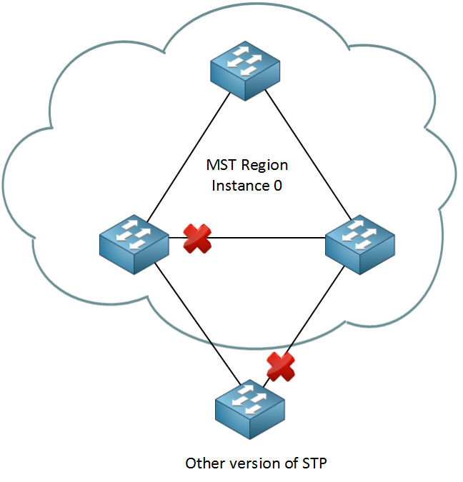
Within the MST region we will have one instance of spanning tree that will create a loop free topology within the region. When you configure MST there is always one default instance used to calculate the topology within the region. We call this the IST (Internal Spanning Tree). By default Cisco will use instance 0 to run the IST. In case you were wondering…its rapid spanning tree that we run within the MST.
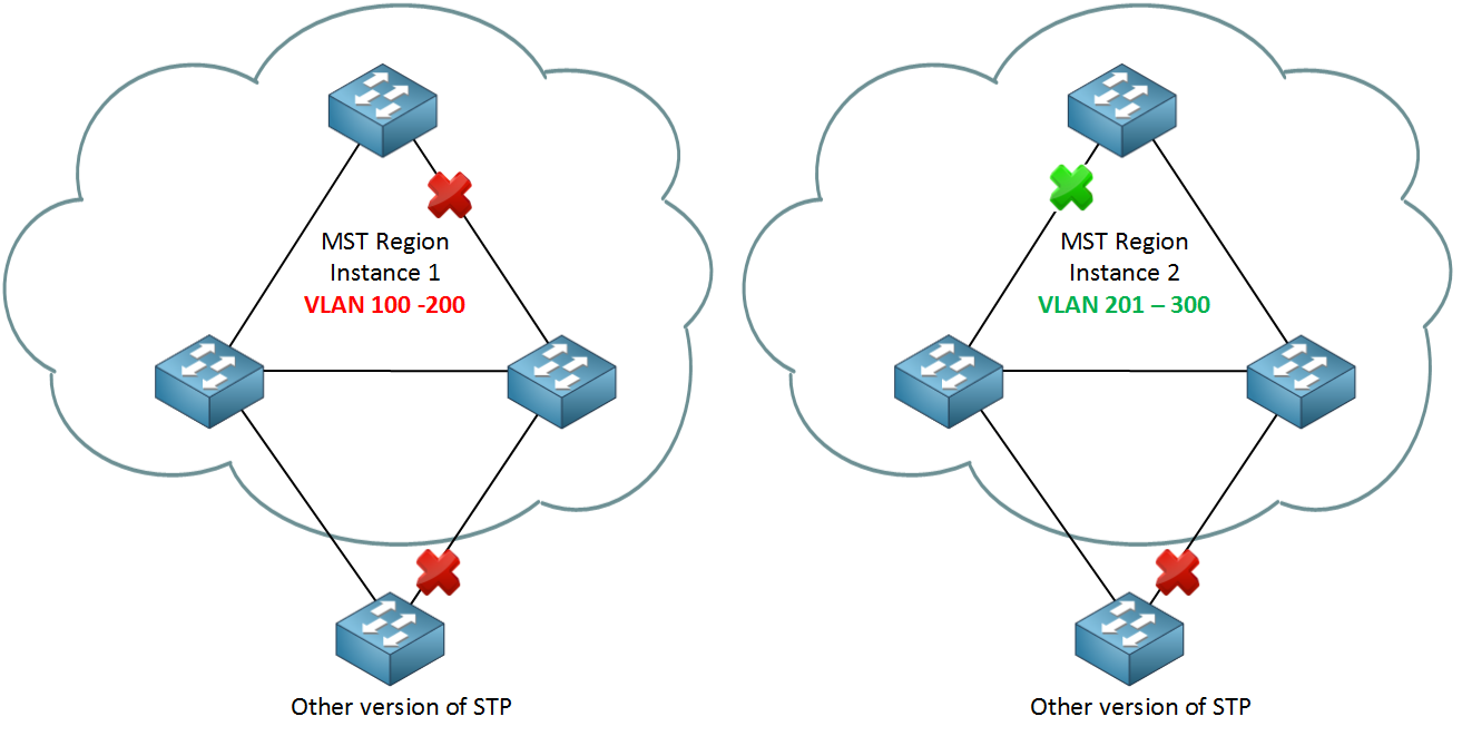
I could create instance 1 for VLAN 100 – 200 and instance 2 for VLAN 201 – 300. Depending on which switch will become root bridge for each instance a different port will be blocked. It could look like this:
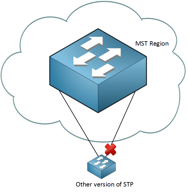
The switch outside the MST region doesn’t see what the MST region looks like. For this switch it’s like it’s talking to one big switch or a ‘black box’:
Does this make sense so far? I hope so! Let’s have some fun with the configuration.
MST Configuration
I will use the following topology:
We’ll start with a single MST region with the following attributes:
- MST configuration name: “IceCream”
- MST configuration revision number: 1 (this is just a number that I made up)
- MST instance to VLAN mapping table:
- Instance 2: VLAN 10, 20 and 30.
- Instance 3: VLAN 40, 50 and 60.
SwitchA(config)#spanning-tree mode mstSwitchB(config)#spanning-tree mode mstSwitchC(config)#spanning-tree mode mstSwitchA#show spanning-tree mst configuration
Name []
Revision 0 Instances configured 1
Instance Vlans mapped
-------- ---------------------------------------------------------------------
0 1-4094
-------------------------------------------------------------------------------SwitchB#show spanning-tree mst configuration
Name []
Revision 0 Instances configured 1
Instance Vlans mapped
-------- ---------------------------------------------------------------------
0 1-4094
-------------------------------------------------------------------------------SwitchC#show spanning-tree mst configuration
Name []
Revision 0 Instances configured 1
Instance Vlans mapped
-------- ---------------------------------------------------------------------
0 1-4094
-------------------------------------------------------------------------------SwitchA#show spanning-tree mst
##### MST0 vlans mapped: 1-4094
Bridge address 0011.bb0b.3600 priority 32768 (32768 sysid 0)
Root address 000f.34ca.1000 priority 32768 (32768 sysid 0)
port Fa0/17 path cost 0
Regional Root address 000f.34ca.1000 priority 32768 (32768 sysid 0)
internal cost 200000 rem hops 19
Operational hello time 2 , forward delay 15, max age 20, txholdcount 6
Configured hello time 2 , forward delay 15, max age 20, max hops 20
Interface Role Sts Cost Prio.Nbr Type
---------------- ---- --- --------- -------- --------------------------------
Fa0/14 Desg FWD 200000 128.16 P2p
Fa0/17 Root FWD 200000 128.19 P2pSwitchA(config)#interface fa0/14
SwitchA(config-if)#switchport trunk encapsulation dot1q
SwitchA(config-if)#switchport mode trunk
SwitchA(config)#interface fa0/17
SwitchA(config-if)#switchport trunk encapsulation dot1q
SwitchA(config-if)#switchport mode trunkSwitchB(config)#interface fa0/14
SwitchB(config-if)#switchport trunk encapsulation dot1q
SwitchB(config-if)#switchport mode trunk
SwitchB(config)#interface fa0/16
SwitchB(config-if)#switchport trunk encapsulation dot1q
SwitchB(config-if)#switchport mode trunkSwitchC(config)#interface fa0/14
SwitchC(config-if)#switchport trunk encapsulation dot1q
SwitchC(config-if)#switchport mode trunk
SwitchC(config)#interface fa0/16
SwitchC(config-if)#switchport trunk encapsulation dot1q
SwitchC(config-if)#switchport mode trunkSwitchA, B & C:
(config)#vlan 10
(config-vlan)#vlan 20
(config-vlan)#vlan 30
(config-vlan)#vlan 40
(config-vlan)#vlan 50
(config-vlan)#vlan 60
(config-vlan)#exitSwitchA(config)#spanning-tree mst configuration
SwitchA(config-mst)#name IceCream
SwitchA(config-mst)#revision 1
SwitchA(config-mst)#instance 2 vlan 10,20,30
SwitchA(config-mst)#instance 3 vlan 40,50,60
SwitchA(config-mst)#exitSwitchB(config)#spanning-tree mst configuration
SwitchB(config-mst)#name IceCream
SwitchB(config-mst)#revision 1
SwitchB(config-mst)#instance 2 vlan 10,20,30
SwitchB(config-mst)#instance 3 vlan 40,50,60
SwitchB(config-mst)#exitSwitchC(config)#spanning-tree mst configuration
SwitchC(config-mst)#name IceCream
SwitchC(config-mst)#revision 1
SwitchC(config-mst)#instance 2 vlan 10,20,30
SwitchC(config-mst)#instance 3 vlan 40,50,60
SwitchC(config-mst)#exitSwitchA#show spanning-tree mst configuration
Name [IceCream]
Revision 1 Instances configured 3
Instance Vlans mapped
-------- ---------------------------------------------------------------------
0 1-9,11-19,21-29,31-39,41-49,51-59,61-4094
2 10,20,30
3 40,50,60
-------------------------------------------------------------------------------So far so good, let’s play some more with MST and change the root bridge:

Within our region I want to make sure that SwitchA is the root bridge. We’ll have to change the priority for the IST (Internal Spanning Tree):
SwitchA(config)#spanning-tree mst 0 priority 4096SwitchA#show spanning-tree mst
##### MST0 vlans mapped: 1-9,11-19,21-29,31-39,41-49,51-59,61-4094
Bridge address 0011.bb0b.3600 priority 4096 (4096 sysid 0)
Root this switch for the CISTLet’s take a look at the interfaces:
SwitchA#show spanning-tree mst 0 | begin Interface
Interface        Role Sts Cost      Prio.Nbr Type
---------------- ---- --- --------- -------- --------------------------------
Fa0/14           Desg FWD 200000    128.16   P2p
Fa0/17 Desg FWD 200000 128.19 P2pSwitchB#show spanning-tree mst 0 | begin Interface
Interface Role Sts Cost Prio.Nbr Type
---------------- ---- --- --------- -------- --------------------------------
Fa0/14 Root FWD 200000 128.16 P2p
Fa0/16 Altn BLK 200000 128.18 P2pSwitchC#show spanning-tree mst 0 | begin Interface
Interface Role Sts Cost Prio.Nbr Type
---------------- ---- --- --------- -------- --------------------------------
Fa0/14 Root FWD 200000 128.14 P2p
Fa0/16 Desg FWD 200000 128.16 P2p
Now I want to make some changes to instance 2 so SwitchB will be root bridge:
SwitchB(config)#spanning-tree mst 2 priority 4096SwitchB#show spanning-tree mst 2
##### MST2 vlans mapped: 10,20,30
Bridge address 0019.569d.5700 priority 4098 (4096 sysid 2)
Root this switch for MST2SwitchA#show spanning-tree mst 2 | begin Interface
Interface Role Sts Cost Prio.Nbr Type
---------------- ---- --- --------- -------- --------------------------------
Fa0/14 Root FWD 200000 128.16 P2p
Fa0/17 Altn BLK 200000 128.19 P2pSwitchB#show spanning-tree mst 2 | begin Interface
Interface Role Sts Cost Prio.Nbr Type
---------------- ---- --- --------- -------- --------------------------------
Fa0/14 Desg FWD 200000 128.16 P2p
Fa0/16 Desg FWD 200000 128.18 P2pSwitchC#show spanning-tree mst 2 | begin Interface
Interface Role Sts Cost Prio.Nbr Type
---------------- ---- --- --------- -------- --------------------------------
Fa0/14 Desg FWD 200000 128.14 P2p
Fa0/16 Root FWD 200000 128.16 P2p
Here’s a fancy picture of instance 2 to show you the port roles. Note that this topology looks different than the one for instance 0.
Last but not least I’m now going to make some changes for instance 3:
SwitchC(config)#spanning-tree mst 3 priority 4096SwitchC#show spanning-tree mst 3
##### MST3 vlans mapped: 40,50,60
Bridge address 000f.34ca.1000 priority 4099 (4096 sysid 3)
Root this switch for MST3SwitchA#show spanning-tree mst 3 | begin Interface
Interface Role Sts Cost Prio.Nbr Type
---------------- ---- --- --------- -------- --------------------------------
Fa0/14 Desg FWD 200000 128.16 P2p
Fa0/17 Root FWD 200000 128.19 P2pSwitchB#show spanning-tree mst 3 | begin Interface
Interface Role Sts Cost Prio.Nbr Type
---------------- ---- --- --------- -------- --------------------------------
Fa0/14 Altn BLK 200000 128.16 P2p
Fa0/16 Root FWD 200000 128.18 P2pSwitchC#show spanning-tree mst 3 | begin Interface
Interface Role Sts Cost Prio.Nbr Type
---------------- ---- --- --------- -------- --------------------------------
Fa0/14 Desg FWD 200000 128.14 P2p
Fa0/16 Desg FWD 200000 128.16 P2p
Let’s compare instance 2 and 3 next to each other:

On the left side you see instance 2 and on the right side is instance 3.
By changing the root bridge per instance we end up with different topologies:
- Instance 2: fa0/17 on SwitchA is blocked for VLAN 10, 20 and 30.
- Instance 3: fa0/14 on SwitchB is blocked for VLAN 40, 50 and 60.
What happens when I add another switch that is running PVST to our topology? Let’s find out!
SwitchD(config)#spanning-tree mode pvstSwitchD(config)#interface fa0/16
SwitchD(config-if)#switchport trunk encapsulation dot1q
SwitchD(config-if)#switchport mode trunk
SwitchD(config)#interface fa0/19
SwitchD(config-if)#switchport trunk encapsulation dot1q
SwitchD(config-if)#switchport mode trunkSwitchD(config)#vlan 10
SwitchD(config-vlan)#vlan 20
SwitchD(config-vlan)#vlan 30
SwitchD(config-vlan)#vlan 40
SwitchD(config-vlan)#vlan 50
SwitchD(config-vlan)#vlan 60
SwitchD(config-vlan)#exitSwitchD#show spanning-tree vlan 1
VLAN0001
Spanning tree enabled protocol ieee
Root ID Priority 4096
Address 0011.bb0b.3600
Cost 19
Port 19 (FastEthernet0/19)
Hello Time 2 sec Max Age 20 sec Forward Delay 15 sec
Bridge ID Priority 32769 (priority 32768 sys-id-ext 1)
Address 0009.7c36.2880
Hello Time 2 sec Max Age 20 sec Forward Delay 15 sec
Aging Time 300
Interface Role Sts Cost Prio.Nbr Type
------------------- ---- --- --------- -------- --------------------------------
Fa0/16 Altn BLK 19 128.16 P2p
Fa0/19 Root FWD 19 128.19 P2pSwitchD#show spanning-tree vlan 10
VLAN0010
Spanning tree enabled protocol ieee
Root ID Priority 4096
Address 0011.bb0b.3600
Cost 19
Port 19 (FastEthernet0/19)
Hello Time 2 sec Max Age 20 sec Forward Delay 15 sec
Bridge ID Priority 32778 (priority 32768 sys-id-ext 10)
Address 0009.7c36.2880
Hello Time 2 sec Max Age 20 sec Forward Delay 15 sec
Aging Time 300
Interface Role Sts Cost Prio.Nbr Type
------------------- ---- --- --------- -------- --------------------------------
Fa0/16 Altn BLK 19 128.16 P2p
Fa0/19 Root FWD 19 128.19 P2pSwitchD#show spanning-tree vlan 40
VLAN0040
Spanning tree enabled protocol ieee
Root ID Priority 4096
Address 0011.bb0b.3600
Cost 19
Port 19 (FastEthernet0/19)
Hello Time 2 sec Max Age 20 sec Forward Delay 15 sec
Bridge ID Priority 32808 (priority 32768 sys-id-ext 40)
Address 0009.7c36.2880
Hello Time 2 sec Max Age 20 sec Forward Delay 15 sec
Aging Time 300
Interface Role Sts Cost Prio.Nbr Type
------------------- ---- --- --------- -------- --------------------------------
Fa0/16 Altn BLK 19 128.16 P2p
Fa0/19 Root FWD 19 128.19 P2p
No comments:
Post a Comment